Steel barrel body plate side expansion rib "two in one" machine (1)
Sik
First, the role of the edge machine and the expansion machine
The pulling edge of the steel barrel body and the expansion rib are the barrel shaping process. The barrel shaping process is one of the requirements of the barreling process itself, such as the setting of the edge-lifting process, the purpose of which is to provide conditions for the assembly of the barrel body and the bottom cover of the bucket; second, the steel drum as a packaging container must have the necessary rigidity. And strength to meet the needs of transportation and storage. The unique edge and expansion machine in the production of steel drums is set to meet the above requirements.
The initial spanning and expansion equipment is a three-machine linkage type of edge-trigger and expansion machine (small-scale machine is not covered in this article). Of course there are more primitive wrenching and expansion equipment. With the development of the barrel technology, there has been a “two-in-one†of the edge-lifting and expansion ribs, until the “three-in-one†steel barrel body shaping equipment for the edge, the expansion rib and the rolling rib. The shaping equipment has evolved from the initial mechanical transmission to the high-tech form of electromechanical hydraulic drive and hydraulic mechanical hybrid drive.
This article mainly introduces the hydraulically driven barrel body expansion rib "two in one" machine, and the old three-machine linkage. The edger and the expansion machine are briefly introduced to compare the advantages and disadvantages between the new and old barrel shaping equipment.
The edge-trigger machine and the expansion machine in the second and third machine linkage
(1) Trimming machine
This type of edger is formed by conventional mechanical spinning. The process of pulling the edge is shown in Figure 1.
It can be seen from Fig. 1 that after the barrel body is sent to the edge-trimming machine by the previous process, the lower roller drives the barrel body to rotate, and the upper roller presses the edge of the barrel around the center of the barrel under the action of the cam. After the edge is finished, under the control of the return spring and the cam, the upper roller is lifted, and the barrel of the pulled side is transferred to the next process under the action of the push barrel cylinder.

Figure 1 Schematic diagram of the edge-trigger process
1-Upper roller; 2-barrel; 3-down roller
The type of edge-trimming machine can adjust the relative distance between the roller at both ends to carry out the edge of the barrel of different heights. The size of the edge value can also be adjusted as required. In addition, the edge-trigger can be used to pull the barrel of any diameter as long as it does not hinder the feeding and withdrawal of the upper roller in the arc direction. Therefore, this edge-trimming machine is suitable for production of multiple varieties and different batches. In addition, due to its working tempo of up to 6 / min, it is commonly used in the 200L barrel flat crimping line.
This edge-trigger also has its fatal shortcomings. If there is a difference in the roller drive system at both ends of the edge-trigger, or the drive pairs at both ends are not worn, the movement of the roller at both ends is not synchronized, which causes a difference in the size of the edge of the barrel. In addition, this method of pressing the edge is easy to produce a wave-shaped edge at both ends of the barrel. These edge defects have a serious impact on the assembly quality of the subsequent assembly process. Therefore, in the normalized seven-layer arc curling, these types of edge-trimming machines cannot meet the strict requirements of the seven-layer circular curling on the size and shape of the barrel.
(two) expansion machine
This type of expansion machine uses mechanical transmission. The assembly of its working parts is shown in Figure 2.
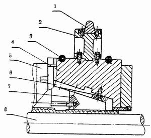
Figure 2 Assembly drawing of the working parts of the old type of expansion machine
1-bulging bar; 2-bulging bar block; 3-slider return spring; 4-slider;; 5-slider rail; 6-abrasion block; 7-wedge block;
The working principle is as follows: when the expansion is started, the pull rod 8 moves to the right, so that the wedge block 7 is moved to the right, and the wedge block 7 drives the slider 4 (8 pieces in total) to move outward in the radial direction, thereby completing the barrel by the expansion block. The process of body expansion. After the reinforcement is completed, the lever is moved to the left and the slider 4 is reset by the return spring. In the figure, the slider guide has two functions: one is to stop the slider in the axial direction so that it does not generate axial displacement; the slider rail is provided with a square groove for guiding the moving direction of the slider 4 and ensuring the circumference. The relative positions of the eight expansion blocks in the direction are correct. The wear block 6 is fixed to the slider 4 and made of 8 pieces of bronze to function as a friction pair.
It can be seen from Fig. 2 that due to the sliding friction between the wedge block and the wear block, and the force required for the barrel expansion is large, in order to reduce the motor power, a wedge block is generally used in the expansion structure (see Fig. 3). ). The big end of the wedge block is fixed adjacent to the connecting rod, so that the force source-cam, firstly swells one rib in the lift, and then swells another rib in the return stroke, that is, the two ribs are swelled twice.

Figure 3 Old-style expansion machine wedge block
In order to meet the requirements of use, the wedge block is generally made of 45 steel forged, and the square bevel should be heat treated to above HRC40.
When the expansion machine is working, the barrel is fed by the feeding trolley. Therefore, before the equipment is operated, the height of the feeding trolley should be adjusted to ensure that the shaft axis of the barrel is coincident with the center line of the expansion rod. If the two do not coincide, the bulge of the barrel is oblique. Under normal circumstances, the user does not require high size and shape of the large ribs. Therefore, this type of bulging machine can meet the requirements of use. In addition, although the two ribs need to swell twice, but still can guarantee a higher production speed, up to 6 / min, still can meet the cycle requirements of the assembly line
Third, the barrel body expansion ribs "two in one" machine
Figure 4 shows a more popular "two in one" machine.

Figure 4 barrel expansion ribs "two in one" machine
1-left vertical plate; 2-trimming plate positioning block; 3-left side plate; 4-low jaw; 5_ base; 6-upper jaw; 7-guide plate; 8-bulging block; - slider seat; 10 - guide column (4 in total); 11 - sliding sleeve; 12 - sliding vertical plate; 13 - right side plate; 14 - expansion bar cylinder; 15 - control cabinet; 16 - pitch handle; 17-right vertical plate; 18-distance disc; 19-photoelectric switch holder; 20-panel cylinder; 21-hydraulic station; 22-post-expansion bar.
The machine uses a programmable controller (PC) and a contactless sensor switch to form a control system. The four parts of machinery, hydraulics, pneumatics and electrical appliances are responsible for each. The machine has the characteristics of stable operation, easy operation and low noise.
As can be seen from FIG. 4, the left side panel 3 is fixed to the left side panel by the positioning block 2. The right side plate is fixed on the sliding vertical plate, and the expansion bar 8 (12 pieces in total) is fixed to the sliding plate by two slider seats. The vertical plate 12 is slid under the action of the hydraulic cylinder-trimming cylinder, and can slide back and forth on the guide post 10 through the sliding sleeve 11.
The hydraulic expansion rib cylinder 14 is used for driving the expansion ribs to be fed radially under the action of the oblique wedge to complete the expansion process. The distance disc 18 is for providing a position signal to the photoelectric switch fixed to the holder 19. Adjusting the distance handle 16 adjusts the distance between the left and right side panels. The end point operating point of the upper jaw 6 can be adjusted by the handle. Adjusting the thickness of the spacer on the lower jaw 4 bracket can adjust the height of the shaft axis of the barrel so that the shaft axis of the barrel coincides with the axis of the edge of the shaft during operation. The guide plate 7 is used to guide the barrel so that the expansion portion smoothly enters the barrel frame. The left and right side plates each have a guiding inclination, and the barrel entering the edge plate is guided, and the defects of the barrel roundness are corrected in advance, thereby reducing the generation of the waste.
The hydraulic circuit of the entire machine tool is provided by the hydraulic station 21.
Below, respectively. The rules and procedures for the use of the two-in-one machine and the gas-liquid circuit are explained.
1. "Two in one" machine use procedures
The "two-in-one" machine performs the barrel shaping requirements shown in Fig. 5 according to the following procedure.
Feeding into the → clamping mechanism into the → feeding and retreating (pull the cylinder into) → expansion of the cylinder into the expansion → expansion of the cylinder retreat → pull the cylinder retreat → clamping mechanism retreat

Figure 5 barrel shaping requirements
1 Schematic diagram of the feeding mechanism is shown in Figure 6.
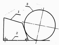
Figure 6 "Two in one" machine feeding mechanism
The piece 1 is bolted to the piece 2, and the relative position of the piece 1 and the piece 2 can be adjusted. The feed rack is driven by a long stroke double acting cylinder.
2 clamping
After the steel drum is fed in, when the jog operation is performed, turn the dial SA2 on the panel of the electric control box of Fig. 7 to No. 2 (clamping), and then press any one of the SB5 or SB6 to clamp the clamping mechanism. Barrel body. Dial the dial to No. 3 (relax) and press the SB5 or SB6 button to release the barrel. When automatic, the signal is sent by the sensor switch installed at the end of the feed, and the clamping mechanism is clamped. After the flange (trimming) cylinder is retracted, the sensor switch sends a signal and the clamping mechanism releases the barrel.
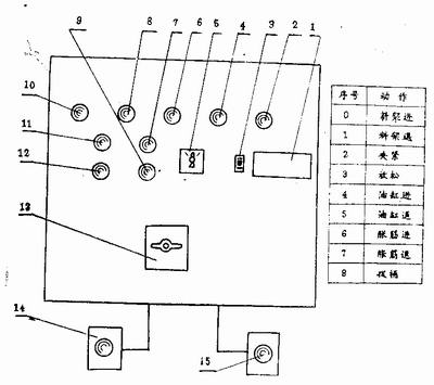
Figure 7 "two in one" electrical control panel
1-Manual condition selection nameplate; 2-over temperature indicator (H1); 3-dial number (SA2); 4-heating indicator light; 5-selection switch (SAI); 6-power indicator light; 7-control Power start button (SB2); 8--control power indication (HLI); 9-total stop (SBl); 10--main motor running indication (HL2); 11-main motor start (SB4); 12-main motor stop; 13 - Total power switch QS1); 14 - Start button SB5; 15 - Start button SB6.
Metal Bottle Opener,Bar Bottle Opener,Hand Held Bottle Opener,Bottle Opener
HOMEARTS INDUSTRIAL CO.,LTD , http://www.homeartschina.com