6.2.3 The function and maintenance analysis of the oil circuit components
The oil circuit is the lifeblood of the machine operation, so it must be in normal working condition at all times, that is to say the entire oil circuit must be unobstructed. To keep the oil line open, every part of the oil circuit must be in normal operation. Take the oil route diagram as an example to analyze the maintenance content of each component in detail.
1. Supply tank. When the fuel tank is working properly, a sufficient amount of oil must be filled in the tank. The amount of oil can meet the requirements can be detected by the oil standard, and some machine oil palm oil can show the amount of oil in the two state of the tank. It should be noted that when the oil level of the fuel tank fails, the fuel tank cover can only be opened and the oil level (or the amount of oil in the lubrication area) can be estimated by observing the oil level or by estimating the oil level in the oil tank. Some poorly sealed tanks are prone to oil leaks, so you should always check the amount of oil in the tank. The oil in the tank should be kept clean. It is best to filter the oil once (with gauze) when changing the oil.
2. The front filter. The front filter is used to filter impurities in the tank. For a long time, impurities in the fuel tank may block the filter holes, making it impossible for oil to enter, so that normal lubrication oil cannot be obtained in the lubrication area. If the filter is found to be dirty, it should be cleaned in time, but be careful not to break it.
3. Oil pump. The oil pump is where the oil gets its energy so that it can flow to where it needs to be. Because most oil pumps use gear pumps. From the drive point of view, this kind of pump will not stop. However, attention should be paid to this type of pump leakage. In particular, the greater the pressure, the more severe the leakage. The other is to prevent impurities from entering the pump and causing gear wear.
4. After the filter. After the filter is used to filter the oil inside the pump. Iron is the main component of impurities. This filter must be absolutely reliable because the oil that goes out is used for lubrication. So post filters generally use ultra-fine filters. Because the filter pores of this filter are small and are easily clogged, they must be cleaned frequently. Otherwise, once blocked, it will make subsequent oil supply difficult.
5. Supply pipe I. The oil supply pipe I mainly transmits oil to the oil valve. Its requirement is to make the oil flow smoothly, so it should not be bent too much, and it should be taken care not to give it to the moving parts. When the oil pipe is not smooth, it is better to replace it with a new pipe. In order to respond to the emergency, steel wire can be inserted to make it smooth.
6. The oil valve. The valve is used to distribute the amount of oil, because the oil level of each oil level is not exactly the same. In addition to controlling the oil distribution, the oil valve should also be able to control the size of the pressure. At present, the oil-dividing valve used in domestic machines can only control the amount of oil, and the oil-dividing valve used in most imported machines can control the pressure. The amount of oil separating valve should be adjusted according to the requirements of the berth. Generally, it should not be arbitrarily adjusted. The oil trap valve is not working properly and can be opened for cleaning. The production of the oil valve has been standardized and can be purchased on request.
7. Supply pipe II. The supply pipe II is responsible for sending the oil in the distribution valve to the part that needs to be lubricated. Some of these oil supply pipes are connected to the oil eye, and the oil is directly injected into the oil eye; some of them are the top of the lubrication point, and the oil is dripped into the part to be lubricated through the oil nozzle. For tubing that is directly connected to the oil eye, if the oil eye is fixed, the tubing can be connected; if the oil eye is not fixed, the tubing should move with the movement of the oil eye. In this case, the flexible tubing should be selected, and the oil tubing should be selected for its pressure resistance. If the pressure is not enough and the tubing cracks during work, the lubrication conditions at the location will be damaged and the consequences will be disastrous. For tubing that is not directly connected to the oil eye, the location of the tubing must be relative to the oil eye (or lubrication site). If it is not relative, the lubrication of this part can not be carried out, especially when it comes to maintenance, it should not be arbitrarily moved. Supply pipe II itself is maintained with oil supply pipe I.
8. Oil eye. Oil suits are the best afterwards to pass oil to the lubrication area. Oil eye generally consists of two parts: the oil hole and the oil tank. The oil flows through the oil hole to the oil tank and then directly into the lubrication area through the oil tank. Therefore, whether the oil hole is unimpeded and whether the position of the oil groove is open directly affects the lubrication effect. Unfiltered oil may block the oil hole. In addition, iron scraps in the lubrication area may also damage the lubrication efficiency of the oil groove. When disassembling and overhauling the machine, clean the oil hole and the impurities in the oil tank. Shaft lubrication generally has oily eyes, and there are no oil suits such as gears, cams, etc. The oil directly drops to the desired lubrication area after passing through the oil supply pipe area. At this time, pay attention to the fact that the oil pipe can not deviate from the lubrication part, otherwise it will cause the accuracy to drop.
9. Return pipe I. Return pipe I generally has two parts: return hole and tubing. The oil return hole and the oil pipe must be unblocked, otherwise the oil in the lubricated part will not leak, and the subsequent lubricating oil will be continuously added, which will cause the oil pressure to rise sharply. When the oil pressure reaches the oil, the oil can pass through the seal ring. Start leaking out through the seal ring. In addition, impurities in the lubrication area cannot leak out, making it difficult to lubricate. In this case, the replacement of the seal ring is of no avail, and must find ways to make the return line I unimpeded. There is no such problem with oil roads that are not oily.
10. Return to the tank. The return tank is used to contain the lubricating oil that flows out of the lubrication area. On small machines, the supply tank and the return tank are common. On large machines, due to the fact that some lubrication sites are too far away from the fuel tank, special return tanks are required. The return tank also serves as a storage lubricant. Because the type of machine lubrication requires a lot of oil. If you rely on the fuel tank only, the fuel tank will have to be made quite large. This will make the machine look clumsy. In addition, it is difficult to return oil from a distant location and it is easy to cause oil leakage.
11. Return pipe II. The return pipe II is used to connect the return tank and the fuel tank so that the return tank oil can quickly return to the tank to allow the oil to re-enter the lubricating oil circuit. If the return pipe II is not smooth, the supply tank will have less and less oil and lubrication will not be able to continue normally. As long as it is a cyclic lubrication, the fuel tank and the return tank are always connected.
6.2.4 Analysis of lubrication
The purpose of lubrication is to reduce harmful friction. The harmful friction mentioned here means that not all parts of the friction are to be lubricated, and some parts of the friction, such as pulleys, are beneficial and therefore cannot be lubricated. To have friction there must be relative movement (or relative movement tendency), so that only the relative movement of the contact surface requires lubrication, which is a basic criterion for the design of the lubricating oil road. From the lubrication point of view, the simpler the oil circuit is, the better the lubrication part is, the better the lubrication is. This requires that the fewer parts of the machine that are in contact with each other, the better, the better the lubrication part. This is another basic guideline for designing oil circuits.
Due to the complex structure of the printing press and the relatively large number of moving parts, this has brought great difficulties to the design of the oil circuit. It is almost impossible to attach a tubing to each lubrication area. Therefore, two kinds of lubrication methods are generally used on the printing machine: one is positioning lubrication, the other is rain lubrication. Positioning lubrication is the direct application of lubrication oil to the lubrication area. This lubrication is suitable for stationary rotary shafts. The lubricated lube oil flows from high to the desired lubricated area as it rains. This type of lubrication has to take into account many lubrication points, and the design must use a large amount of oil, which increases the possibility of oil leakage.
The oil pressure required for positioning lubrication is greater, and the higher the machine speed, the greater the required oil pressure. Therefore, the positioning oil for lubrication needs higher compressive strength. The rain lubrication does not require large oil pressure, as long as the oil inside the tank can be added to the top of the required lubrication components. However, the speed of the machine changes, and the amount of oil used varies accordingly. The above is the third basic rule to follow in designing the oil circuit.
Is the more lubricant better? Some masters always think that the more lubricating oil the better, refueling always make the most of the increase, wait for the lubrication of the oil tank, think that this is the best lubrication effect. In fact, this is inappropriate and unnecessary. Lubricating oil has a certain viscosity, so it will also cause a certain amount of energy consumption, so the lubricating oil should not be too much.
Lubricating oil loss has the following several ways: First, deterioration. Lubricating oil in the lubricated area can cause a chemical reaction and lose its performance. The second is leakage. Although seals are used in the lubrication area, there is always more or less oil penetrating out of the edge of the seal. Due to the loss of lubricating oil, the oil in the lubrication area needs to be continuously replenished. Many machines are equipped with a delay device on the oil path to ensure regular oiling.
The choice of lubricants. The size of the oil used in different machines is not the same. Such as high-temperature lubricated parts need to use a large viscosity of the lubricating oil, and low-temperature need to use a small viscosity of the lubricating oil. This is because the temperature is high and the viscosity of the lubricant is reduced; when the temperature is low, the viscosity of the lubricant is increased. The oil in the lubrication area must have a certain viscosity so that it can adhere to the contact surface. Take the machine as an example. If you use 40th oil in winter, you should use 50th oil in summer. For the air pump, the viscosity of the selected oil should be greater because it operates at a high temperature.
6.2.5 Oil Lubrication and Grease Lubrication
Oil lubrication and bulge lubrication are the two most widely used lubrication methods on the machine, but they have their own emphasis in practical use. Due to the large fluidity of the oil and the ability to continuously replenish, the heat generated by the friction can be diffused out in time. Therefore, the oil lubrication is suitable for high-speed, heavy-duty mechanical lubrication. The poor flow of grease, the heat generated by the friction is completely absorbed, and can not be diffused out, so grease lubrication is suitable for lubrication of low-speed, light-loaded machinery. Grease lubrication is a manual lubrication. Due to the increased fluidity of the grease after heat absorption, it easily overflows from the lubrication site. However, it cannot be continuously replenished by itself. Therefore, it is necessary to check the bulge lubrication regularly.
All the open and close teeth cams do not require lubrication and all springs require lubrication.
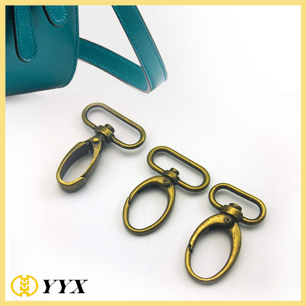
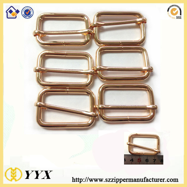
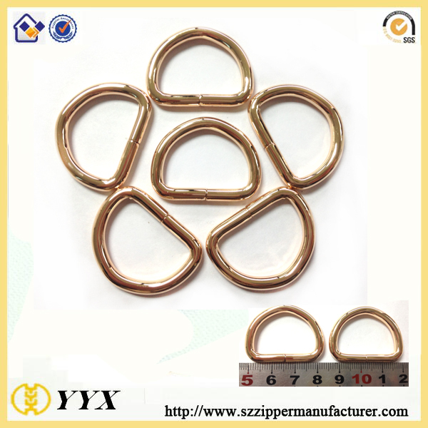
Buckles, Snaps, Slides, D-Rings, Loops, Fasteners, and other General Hardware are our main products. The bag metal buckles are made from zinc alloy or iron. Applications include Tents and Camping Equipment, Military, Bag, Animal Harnesses, Pet Leashes, Collars and Harnesses, Luggage, Straps and Fashion.
Professional, customized design and development services are welcome! Whether you are looking for a new part concept or you just need to reduce cost, our experienced engineering Team is ready to help with any project. Send us artwork in picture, PDF or AI format, and we will give you perfect product!


*Related Products:swivel metal hook,d ring,Carabiner hook,adjuster buckle.
Metal Buckle,Metal Belt Buckles,Customized Buckles
Shenzhen Yiyixing Zipper Manufacture Co.,Ltd , https://www.yyxzip.com